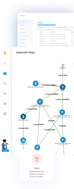
What Is Network Topology Mapping?
Network topology mapping analyzes and discovers all elements or nodes linked to a network in order to visualize and troubleshoot communications. IT Mapping visualizes the physical and logical topologies in a graphical plot, thus simplifying the monitoring of performance and locating faults. It helps to break topologies into smaller, trackable portions, aiding in their navigation which may otherwise be different to understand, due to cabling complexities.
A network topology map contains network diagrams, flowcharts, device inventories, the network’s weak and strong points, and a wealth of additional information about the devices in the network. The IT system mapping scans the network bandwidth and latency, interprets the information gathered, and creates alerts where necessary.
Network topology is the anatomy, arrangement, or layout of telecommunication devices. These devices are represented as nodes, and the topology highlights the relationships between the nodes. Nodes are classed as hardware equipment on your network including both static and mobile devices, switches, and routers.
Table of Contents
Toggle
Types of Network Topology
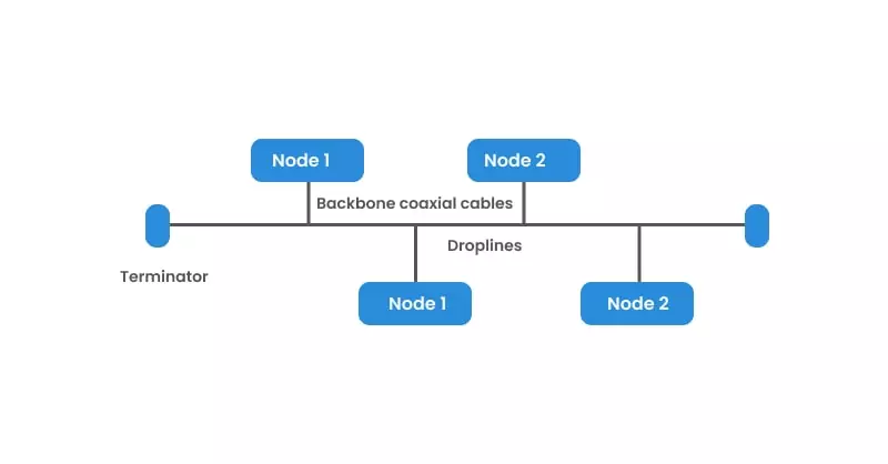
Bus Topology
In a bus topology, the computers are all connected to one single cable. Only the addressee accepts and processes the message when one computer sends a signal using the cable. Other computers on the network acknowledge the message, but disregard it.
Bus topology is often used when a network installation is temporary or small in scale. Unidirectional data flow in bus topology makes problem identification tricky, and heavy network traffic slows it down. While the failure of one node does not affect the network, failure of the bus system as a whole will cause the entire network to crash.
A linear bus topology has two endpoints, and a distributed bus topology has more than two endpoints.
Ring Topology
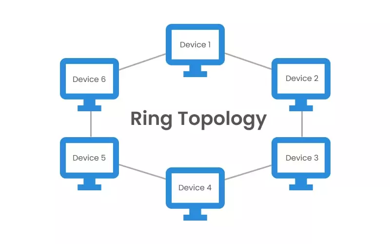
Each computer is connected to the next computer in a circular arrangement; the last connects to the first in order to form a closed loop. Each device serves as a repeater that strengthens the signal received from the previous device.
Read our guide Microsegmentation beginners guide
In a ring topology, messages flow in one direction only, using tokens to pass information from one computer to another. The token is a small packet that is modified with the intended message and the addressee’s details. The token helps each device identify for whom the message is intended. When a piece of information is not intended for a particular computer, the token sends it to the next computer and so on, until it reaches the addressee.
Due to its circular arrangement, ring topology is more complex to troubleshoot than some other topologies, such as the bus topology. Unlike the bus topology, in a ring topology the failure of one computer can affect the entire network, and adding or deleting a device disturbs the network’s performance. In addition, since information has to pass from one computer to another, the network is slower.
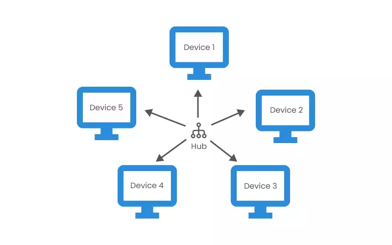
Star Topology
In a star topology, each device is linked to a central controller through its dedicated point-to-point cable. The devices communicate with a central controller that resends the message to the appropriate addressee(s).
This central controller—also called the hub, host, or server—can be active or passive. While an active hub regenerates a signal and sends it to all the computers connected, a passive hub does not regenerate the signal but merely acts as a connection point.
Star topology is easily modified by adding or deleting computers or nodes, and this process does not affect the overall network performance. Hence, a hub with larger ports can be easily installed. However, the failure of the central hub affects the whole network. The central hub can be installed with coaxial cable, optical fiber, or twisted pairs.
Mesh Topology
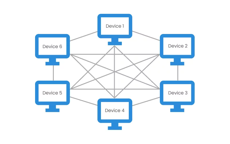
The mesh topology is a robust, fully connected topology used in a WAN, or wide area network. Every device has a dedicated point-to-point link to all other devices, with the result that each computer must have input/output ports. This dedicated P2P link system eases fault identification and isolation, and prevents traffic between computers.
In a mesh topology, data is transmitted through routing and flooding. Routing uses the shortest path between source and destination to transmit data, while flooding sends data from the source to all the network nodes, but only the addressee accepts the data.
Mesh topology can be divided into two subtypes: full mesh and partial mesh. Each device in the workstation is directly connected to the others in the full mesh architecture. On the other hand, in the partial mesh architecture some devices are connected to the nodes with whom they exchange the most data, while others are connected to all nodes. Due to the quantity of required input/output ports and cabling, mesh topology is expensive.
Tree Topology
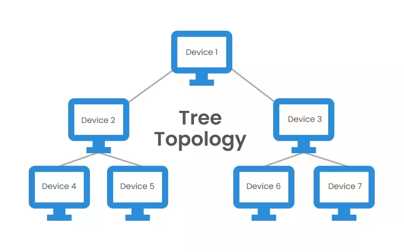
A bus system connects numerous star topologies in a tree-branch configuration to form the tree topology. A single “hub” node at the top of the network is connected to several lower-level nodes via point-to-point links. Additionally, these lower-level nodes are linked to one or more nodes (downlines) in the following level. The “branching factor” of the tree is the fixed number of nodes connected downline.
Hybrid Topology
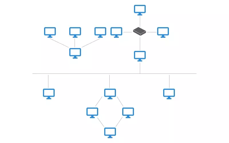
Hybrid topology occurs when two or more types of topologies are connected. In a single establishment, one department of an establishment might be using a ring topology, while another department opted for a bus topology. These two networks can connect to a star topology’s central hub. However, the architecture of the resulting arrangement does not exhibit any standard network topologies. Hybrid topology’s robust architecture often makes it costly, since it requires extensive infrastructure, cooling, and cabling.
Point-to-Point Topology
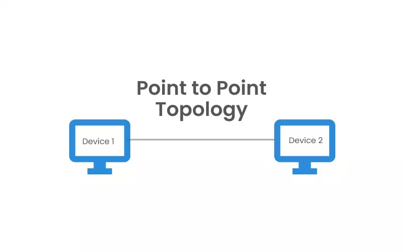
Also referred to as P2P, point-to-point is the most basic network topology and consists of a direct connection between two computers and peripheral devices. The communication medium is monopolized in this topology since it is not shared, and there is no need for a device identification mechanism.
Daisy Topology
A daisy topology can come in linear or ring forms. Like in a ring topology, when a computer sends a message, each computer bounces the message in the chain until it reaches its destination. However, whereas the ring topology closes up through a circle of connections (see Figure 1,) a daisy topology has an endpoint that makes it easy to add new devices and nodes to the network (see Figure 3.) This topology is also known as chain topology because it connects the network devices in a sequence.
Why Perform Network Topology Mapping?
Network mapping provides administrators with crucial performance insights, such as device status, physical connections, and traffic metrics, so that administrators can fix issues faster, thus maximizing uptime. With mapping, a potentially devastating issue can be managed before problems occur. For example, if there is a security breach on any of the devices in the network, mapping solutions will indicate a change in the traffic and data flow, signaling to the administrator that there is an issue before that issue is encountered by any network user.
Prompt responses to network and device faults are essential to the growth of any telecommunications organization, and quick detection of these faults and their root cause is the crux of network topology mapping. Network topology mapping, therefore, improves disaster planning and enhances network control and protection.
Network Topology Mapping Techniques
There are three main network topology mapping techniques: SNMP, active probing, and route analytics software.
SNMP
SNMP is an acronym for Simple Network Management Protocol. It is an Internet Standard mapping technique that scans network devices automatically and exposes technical data as variables on the managed systems. In order to describe the system status and configuration, these variables are then organized in a management information base (MIB.)
The SNMP application layer (OSI Layer 7) can also access and change the system variables on the network devices. Furthermore, SNMP gathers the information discovered, including the number of active ports and temperature value, and uses them to create objects in the network map. There are three versions of SNMP (SNMPv1, SNMPv2, and SNMPv3,) with SNMPv2 being the most frequently deployed protocol version.
Active Probing
Active Probing is a technique that diagnoses networks by sending probe packets into the network to gather information. It then uses the data retrieved from the system’s logical topology architecture (called the traceroute-like methods) or its IP to create a network map. Active probing relies on the data plane of the network and its router adjacencies to map its topology. One advantage of active probing is its exactitude, because the paths returned by probes are the forwarding path that data takes through the network.
Route Analytics Software
Route analytics software is an automated mapping technique that explores the topology of a network using Layer 2 and Layer 3 information to map and discover devices connected to the system. For clarity, Layer 2 is the data link packet of a network system, while Layer 3 gathers the IP addresses of the network infrastructures.
While SNMP observes only the system interfaces and links, route analytics software explores the network further by providing complete routing history, traffic monitoring, end-to-end statistics, and detailed performance diagnostics.
Key Features of Network Topology Mapping Tools
Network topology mapping tools offer several key features that help IT teams visualize, monitor, and optimize their network infrastructure. These features ensure efficient management, troubleshooting, and security of the network.
- Automated Discovery: Automated discovery scans the entire network to identify and map all connected devices, reducing manual effort. This feature ensures that network diagrams remain up to date even as the network evolves.
- Real-Time Monitoring: Real-time monitoring provides continuous oversight of network health and performance. It tracks changes in topology, device status, and traffic flow, alerting administrators to potential issues before they cause disruptions.
- Layered Mapping: Some tools offer multi-layered mapping, which enables users to view physical, logical, and application-layer connections separately. This improves network visibility and helps diagnose issues more effectively.
- Customizable Visualization: Interactive and customizable network diagrams allow IT teams to organize views based on hierarchy, connectivity, or device roles. Many tools also offer zooming, filtering, and color-coded indicators for better clarity.
- Integration With IT Management Systems: Modern topology mapping tools integrate with security information and event management (SIEM), IT asset management (ITAM), and network monitoring solutions. This integration helps correlate network topology with security threats and performance metrics.
- Historical Data and Change Tracking: Many tools log past network configurations, enabling teams to compare current and historical topologies. This feature helps identify trends, troubleshoot recurring problems, and plan for network expansions.
- Security and Compliance Insights: By mapping all devices and connections, topology mapping tools help identify unauthorized devices, misconfigurations, and compliance violations. Some tools also include security analytics to detect anomalies and vulnerabilities.
- Automated Alerts and Reporting: Advanced tools provide automated alerts when devices go offline, bandwidth thresholds are exceeded, or security issues arise. They also generate reports on network performance, usage trends, and risk assessments.
7 Notable Network Topology Mapping Tools
1. Faddom
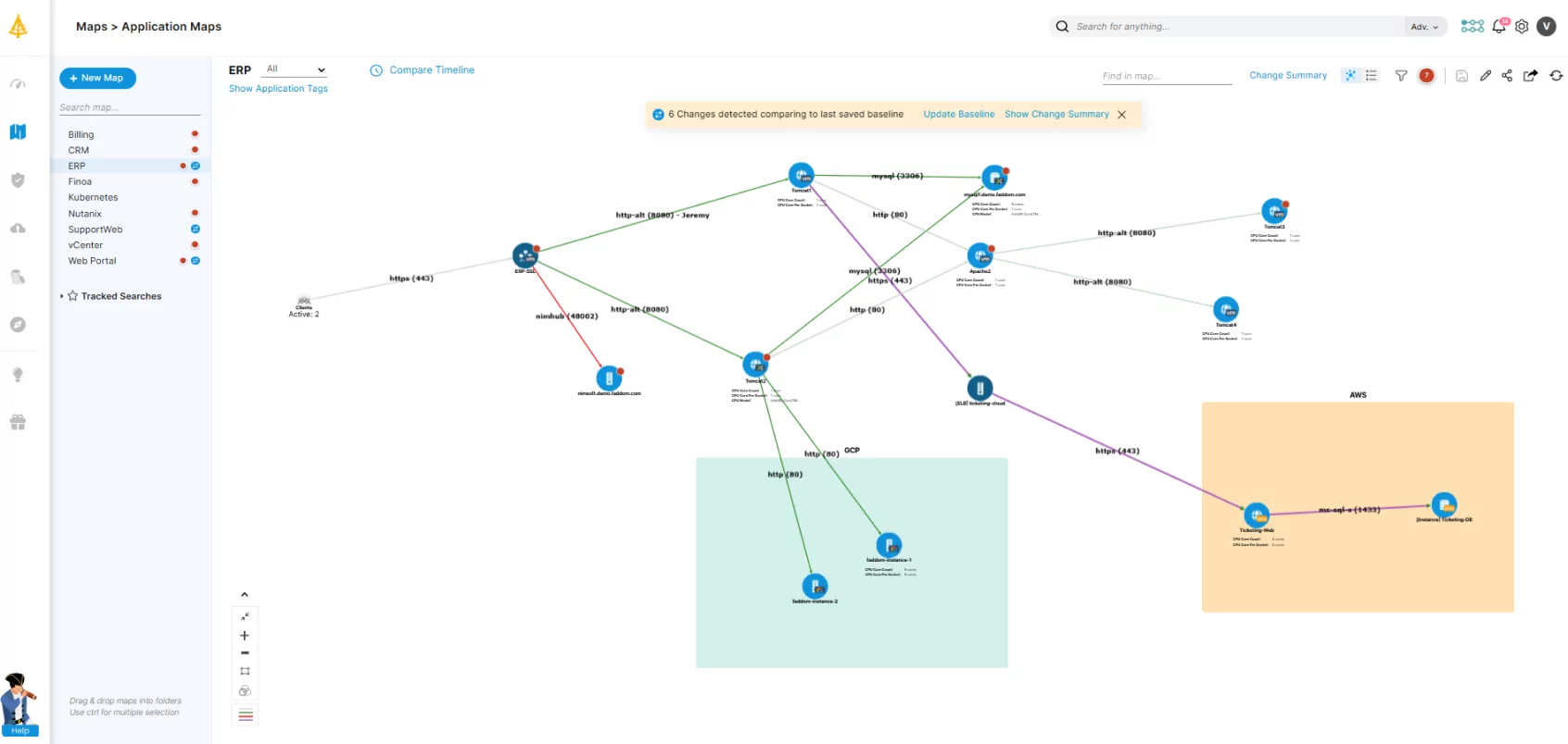
Faddom is an agentless network topology mapping platform that automatically maps both cloud and on-premises networks, regardless of the topology type, in under an hour. It provides IT teams with real-time visibility into their entire infrastructure, enabling them to optimize performance, troubleshoot issues faster, and enhance security.
Key features include:
- Agentless and passive application mapping: Automatically detects and visualizes dependencies without requiring agents.
- Scalability: Adapts to organizations of any size, from small IT teams to large enterprises.
- Security-focused design: Operates without active network scanning, reducing security risks.
- Hybrid environment support: Maps dependencies across on-premise, cloud, and hybrid infrastructures.
- Change impact analysis: Helps IT teams assess the risks of infrastructure modifications before implementation.
- Seamless Integrations: Connects with ITSM and SIEM tools like ServiceNow for enhanced management.
Learn more about Faddom for application mapping or take the next step and book a demo with our experts!
2. OpManager Network Mapping
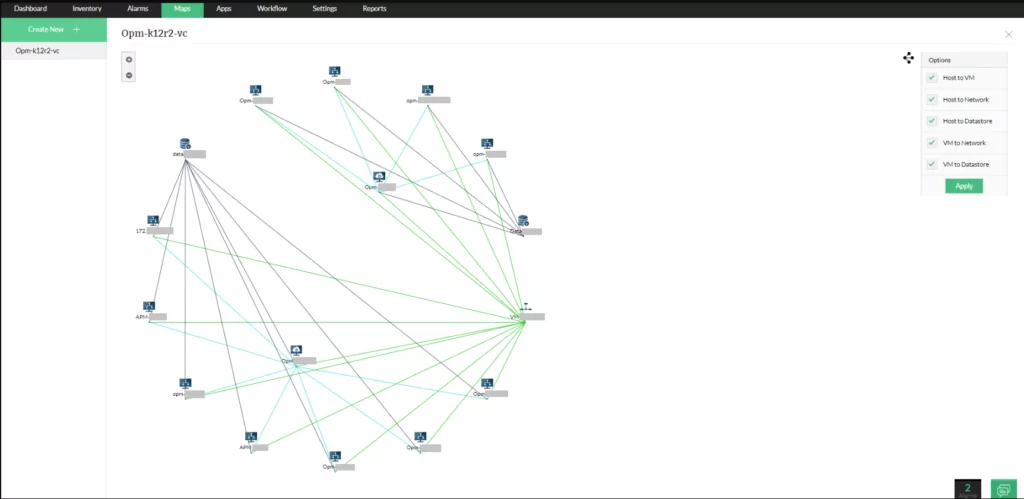
OpManager is a network monitoring tool that provides visibility into network performance and infrastructure. It automatically discovers and maps all network devices, including routers, switches, firewalls, servers, and wireless networks. The tool supports both physical and virtual environments and integrates with IT management systems.
Key features include:
- Automated network discovery: Identifies and maps all connected network devices without manual input.
- Network monitoring: Tracks device health, availability, bandwidth usage, and performance in real time.
- Layer 2 and virtual topology maps: Visualizes physical and logical connections between devices.
- Wireless network monitoring: Monitors access points, WiFi strength, and wireless traffic.
- WAN and Cisco ACI monitoring: Provides visibility into WAN link availability and Cisco ACI infrastructure.
Source: ManageEngine
3. N‑able N-central Network Mapping

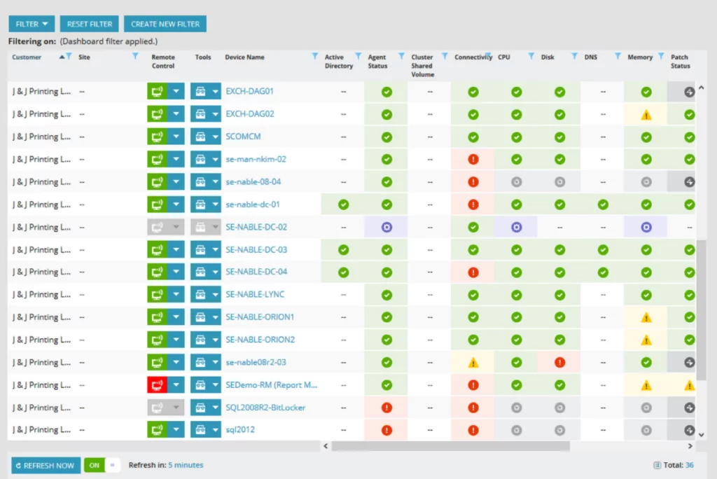
N‑able N-central provides a network mapping solution for managed service providers (MSPs) and IT professionals. The tool automatically discovers, maps, and visualizes network topologies, replacing manual spreadsheets. It continuously updates network diagrams to reflect changes, helping IT teams maintain visibility.
Key features include:
- Automated discovery and mapping: Identifies all network devices and generates real-time topology maps.
- Dynamic visualization: Updates network diagrams automatically when devices are added or removed.
- Troubleshooting: Highlights critical connections to help diagnose performance issues.
- Scheduled scans: Detects configuration changes and keeps network maps up to date.
- Centralized dashboard: Provides a single interface for monitoring and managing network infrastructure.
Source: N‑able
4. SolarWinds Network Topology Mapper

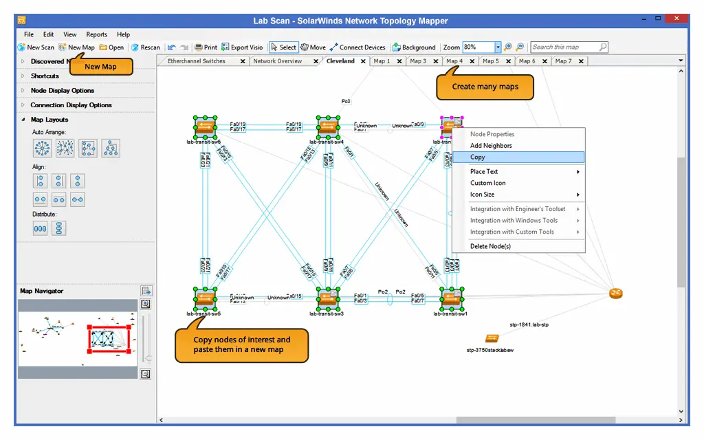
SolarWinds Network Topology Mapper (NTM) is an automated network mapping tool that helps IT teams discover, visualize, and maintain up-to-date network diagrams. Using protocols like ICMP, SNMP, WMI, and CDP, NTM scans the network to identify devices and connections.
Key features include:
- Automated network discovery: Identifies and maps all network devices without manual input.
- Topology updates: Detects and reflects changes in the network automatically.
- LAN topology mapping: Automates the diagramming of LAN environments.
- Logical network diagram creation: Builds network topology diagrams for easy visualization.
- Network inventory management: Tracks and documents network assets.
Source: SolarWinds
5. WhatsUp Gold’s Network Mapping

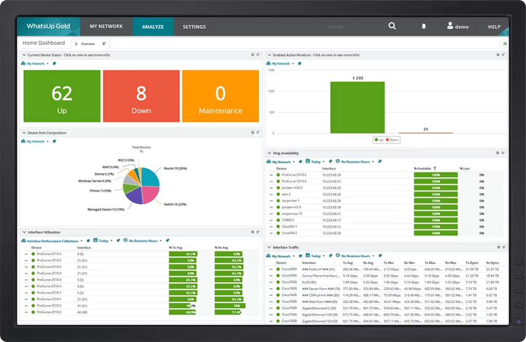
WhatsUp Gold’s network mapping tool provides visualization of network topology using Layer 2 and Layer 3 discovery techniques. It automatically discovers all connected devices and their dependencies, creating interactive maps that update as the network evolves.
Key features include:
- Automated discovery and mapping: Uses SNMP, ARP, ICMP, CDP, LLDP, and other protocols to identify network devices and their connections.
- Topology updates: Updates network maps as devices are added, removed, or modified.
- Device dependency mapping: Detects downstream dependencies to prevent alert storms and improve fault isolation.
- Customizable network maps: Allows users to add images, text, and links, or organize devices into logical groups.
- Bandwidth utilization visualization: Provides a heat map of interface usage, highlighting potential congestion points.
Source: WhatsUp Gold
6. Paessler PRTG Network Monitor

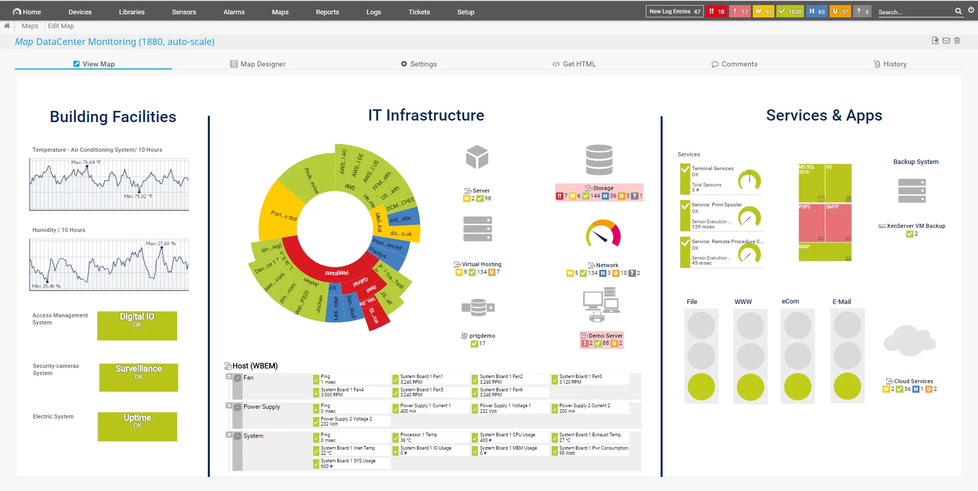
Paessler PRTG Network Monitor is a monitoring solution that provides visibility into IT infrastructure, including networks, servers, applications, and cloud services. Using SNMP, WMI, SSH, and flow-based traffic analysis, PRTG automatically discovers and monitors all connected devices, alerting administrators to potential issues.
Key features include:
- Network monitoring: Tracks devices, traffic, and applications across the IT environment.
- Automated discovery and visualization: Identifies network components and maps them in real time.
- Customizable dashboards and maps: Provides a live overview of network health with interactive visuals.
- Alerts and notifications: Sends alerts via email, push notifications, or custom API triggers.
- Multi-protocol support: Monitors infrastructure using SNMP, WMI, SSH, packet sniffing, and flow analysis.
Source: Paessler
7. Intermapper

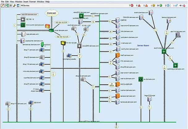
Intermapper is a network monitoring and mapping solution that provides visibility into IT environments. It automatically discovers all IP-enabled devices and creates live, color-coded network maps, helping IT teams identify and resolve issues.
Key features include:
- Automated network discovery and mapping: Detects and visualizes network devices, connections, and statuses.
- Status monitoring: Uses color-coded indicators to highlight active and offline devices.
- Customizable network maps: Supports hierarchical maps, sub-maps, and various icons to organize network views.
- Alerts and notifications: Sends alerts via email, text, or sound when network issues arise.
- Network traffic analysis: Monitors bandwidth usage with Intermapper Flows, analyzing NetFlow, sFlow, and jFlow data.
Source: Intermapper
Conclusion
Network topology mapping is essential for maintaining efficient, secure, and scalable IT infrastructure. Organizations can optimize performance, quickly detect issues, and strengthen security by visualizing network components and their relationships. Automated tools simplify this process, ensuring accurate and up-to-date topology maps that support informed decision-making and effective network management.

Lanir specializes in founding new tech companies for Enterprise Software: Assemble and nurture a great team, Early stage funding to growth late stage, One design partner to hundreds of enterprise customers, MVP to Enterprise grade product, Low level kernel engineering to AI/ML and BigData, One advisory board to a long list of shareholders and board members of the worlds largest VCs
Tips from the Expert
In my experience, here are tips that can help you better adapt to the topic of network topology mapping:
-
Incorporate real-time monitoring
Use real-time monitoring tools to continuously track network performance and topology changes, enabling immediate detection and response to issues as they arise.
-
Utilize synthetic testing
Implement synthetic testing methods to simulate network traffic and stress-test the network topology, helping identify potential bottlenecks and failure points before they impact users.
-
Integrate with security tools
Ensure your topology mapping integrates seamlessly with your security information and event management (SIEM) systems to enhance visibility into potential security threats and vulnerabilities.
-
Adopt a layered mapping approach
Create multiple layers of network maps focusing on different aspects such as physical connections, logical flows, and application-level dependencies to get a comprehensive understanding of the network.
-
Leverage machine learning for anomaly detection
Implement machine learning algorithms to analyze network traffic patterns and detect anomalies that could indicate emerging issues or security threats.
See Additional Guides on Key Access Management Topics
Together with our content partners, we have authored in-depth guides on several other topics that can also be useful as you explore the world of access management.
ABAC
Authored by Frontegg
RBAC
Authored by Frontegg
User Management
Authored by Frontegg
